Blinketto
Table of Contents
Background
Some years ago, during lunchbreak at work we walked passed a GameStop store. Out of pure boredom we sometimes went in and over time, I bought a bunch of Nintendo PixelPals (yes, the nostalgia is strong in me). PixelPals are battery-powered toys that do nothing but light up.
So of course the very first idea was to make them not use batteries anymore, cause who wants to constantly change batteries in your living room decoration? Plus the PixelPals have their mostly fixed location, so there is no need to keep them mobile and battery-powered.
And so I embarked on the journey to build my own what i now know is called “LED controller”.
Goals
Whatever I built should
- be able to power up to 8 PixelPals (8 because that is how much space i have on my shelf and how many good looking PixelPals even exist).
- make them blink and show some rudimentary patterns.
- detect on its own how many and which of the 8 ports are plugged in.
Note that at the time of building this, there was no USB adapter for PixelPals yet. And even today, in 2023, the adapter was only ever sold in the USA and is currently out of stock everywhere, apparently reaching horrendous prices on eBay. Since I wanted to learn about electronics, waiting for these adapters to be available in Europe was not an option for me.
Journey
When starting this project I had very, very little experience in working with Arduinos. Never had designed a PCB myself, let alone used micro controllers besides a standard Arduino Uno.
Blinketto 1.x
At first my idea was super simple:
All I need is some transistors, right? Wire them all up in parallel, use the GPIO pins of an Arduino on the gate to control the brightness and Bob’s your uncle.
But I (with zero electronics know-how) did not anticipate a whole lot of downsides (like not having Pulse Width Modulation (PWM) to dim the PixelPals) and also simply not knowing what kind of transistors I would need.
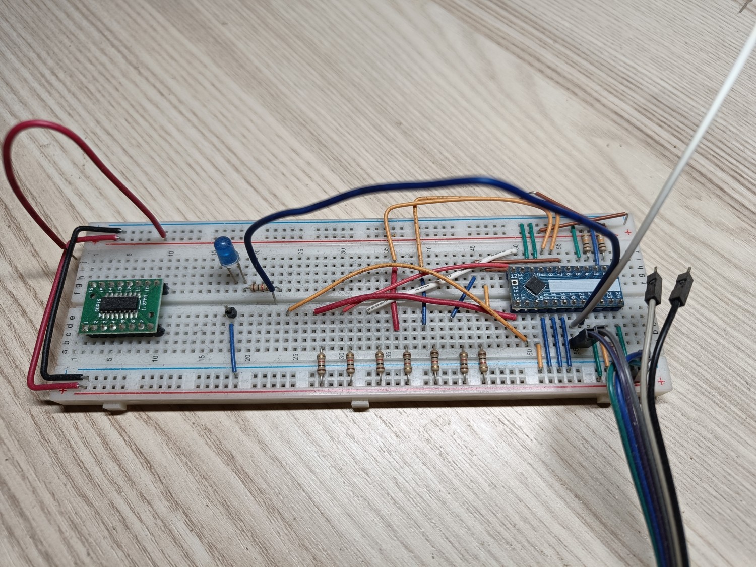
At this stage I was mostly working on breadboards to see if my idea would work out at all. No photos exist of this stage anymore, so here’s a symbolic photo from a bit later when I tried some other things:
I learned quickly that to do it right and not end up with a rat’s nest of wires, I had to design my own PCB…
Blinketto Next Generation
Blinketto 2.0
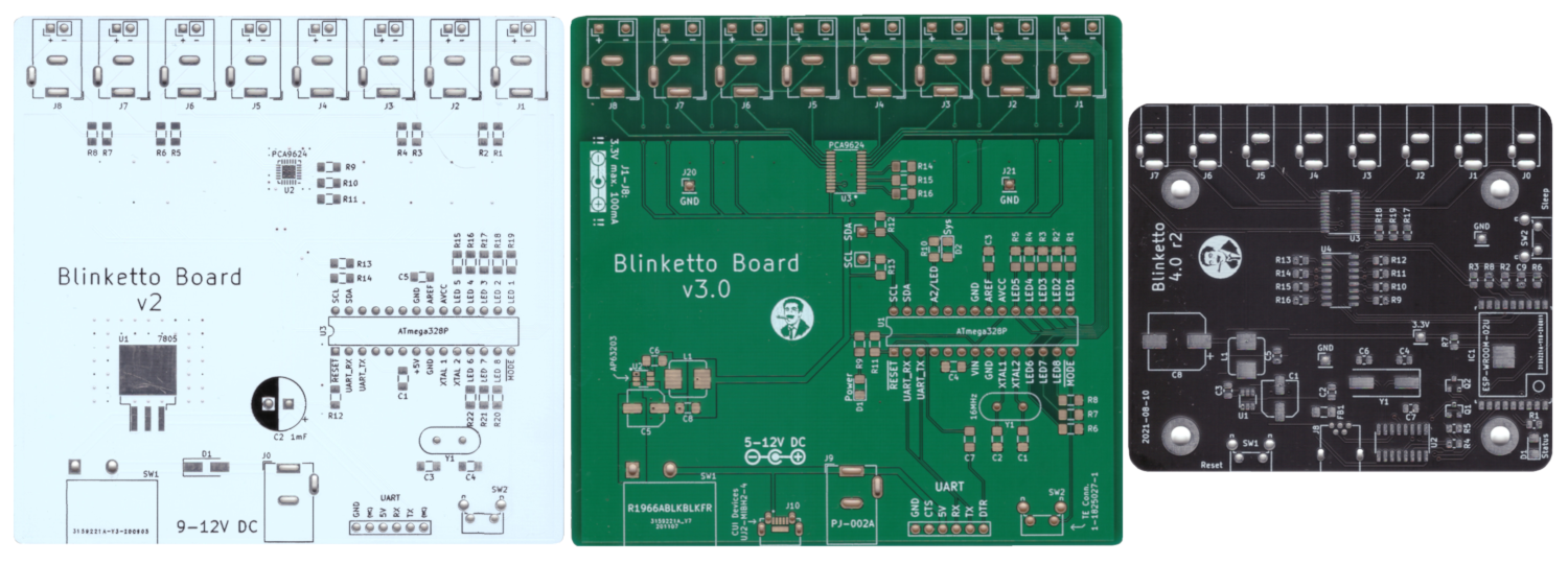
Version 2.0 was the first “real” version. It’s also the first time ever that I designed a PCB in KiCAD and had it produced by a Chinese PCB manufacturer.
On the PCB we can see my train of thought:
- I used a big fat linear voltage regulator to get down from the 9/12V DC to the 5V I needed. I planned on using one of my existing 9/12V power bricks, hence the barrel jack and 7805 regulator. Note the giant heatsink solder area: At this stage I was still very worried about the wattage my device would have to handle.
- I still planned on using an ATmega chip. It’s the same chip as on an Arduino Uno, so seemed the easiest choice.
- I gave up on dealing with individual transistors and instead discovered that ready-made LED controller chips exist. I chose one that fit my bill (PCA9624), but was super hard to solder for a newbie like me and over the next revisions of the PCB, I would try to make the QFN chip easier to solder.
- The board was made to fit into a ready-made metal enclosure. I was worried about the heat that the LED driver chip might give off, so I planned on, if need be, use the case as an additional heatsink.
This board worked fine as a first experiment, but had a number of downsides:
- The white PCB is ugly as sin. Even though it would have been hidden entirely within the case, it’s still just terrible to look at, plus it’s super hard to see PCB traces. Use white only if you use your PCB as a design element, never for functional boards.
- I still had trouble even interfacing with the PCA LED driver. Debugging the I²C signals was near impossible, as there was no (easy) access to the necessary pins.
- There was no debug output anywhere. If something in my code didn’t work, I had no way of seeing anything. It was basically coding blind.
Blinketto 2.1
This revision
- adds additional pins to hook an oscilloscope into the I²C traffic,
- adds a status LED for debugging / healthchecks,
- adds a power LED,
- significantly improves the silkscreen.
This revision is also the first board where I ever used the Groucho Marx picture as my “logo”.
This board taught me
- use a different footprint for the LED driver, it’s just not solderable by hand…
- my attempt at building a UART pin header (to allow me to program the ATmega chip) was borked in so many ways, from broken restarts to timing issues and whatnot.
Blinketto 2.2
(is lost to history)
Blinketto 2.3
This revision improves the problems from 2.1:
- a better UART connector with properly connected CTS/CTR pins,
- a smaller bulk capacitor, as the larger one was simply overkill,
- the diode to prevent wrongly polarized barrel jack connectors was removed: the voltage regulator is already protected against reverse polarity.
I purchased TSSOP variants of the LED driver and so was also able to change its footprint, making soldering so much easier for me.
Blinketto 3.0
In this revision I realized that powering the device with a 12V barrel jack just sucks. Instead I pivoted to using USB (i.e. 5V) and use a switching regulator instead of a linear one. This keeps the voltage drop small enough and reduces the waste heat considerably.
Note that I used MiniUSB on purpose: most of the cheap micro USB connectors fit way too tight for my liking and USB-C connectors are an unnecessary hassle for hand soldering PCBs.
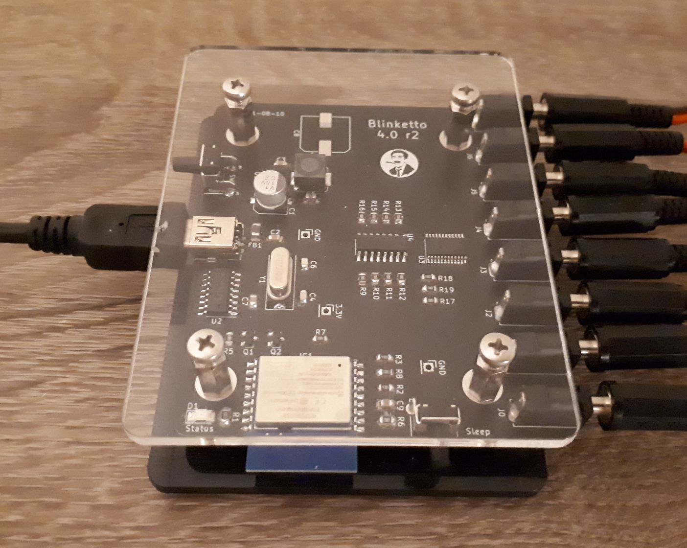
Blinketto 4.0
Between 3.0 and 4.0, I worked on another project and for that I purchased a whole bunch of laser-cut acrylic plates. I used these as the “case” for my project and once that was finished, I had so many laying around that I wanted to convert Blinketto into the same form factor.
Additionally I got more comfortable with ESP8266 micro controllers and so the whole Blinketto board was redesigned from the ground up.
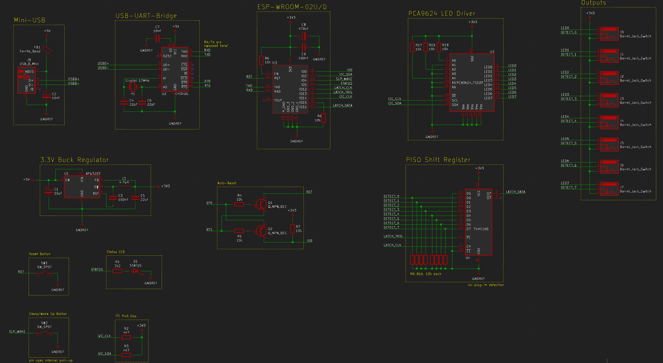
This version
- has WiFi support,
- uses much smaller connectors (3,5mm connectors) to fit all 8 on the PCB without interfering with the mounting poles,
- has a USB<->UART converter chip on board to allow programming by just plugging Blinketto via USB into my computer,
- has a shift register to handle the plug-in states for the 8 outputs. The ESP8266 does not have enough built-in GPIO pins to connect all 8 outputs straight to it, so a shift register was added to hold the state,
- has a new button on the side to put Blinketto into sleep mode (i.e. set brightness to 0%).
At this point I also switched from using the Arduino IDE to VSCode, which removed some convenience layers but made things easier to understand for me as a developer. Plus it was nice to work on the command line and not have this .ino file concept and magic file merging that the Arduino IDE does.
Do not misunderstand: I adore what Arduino is doing, but I simply outgrew their IDE.
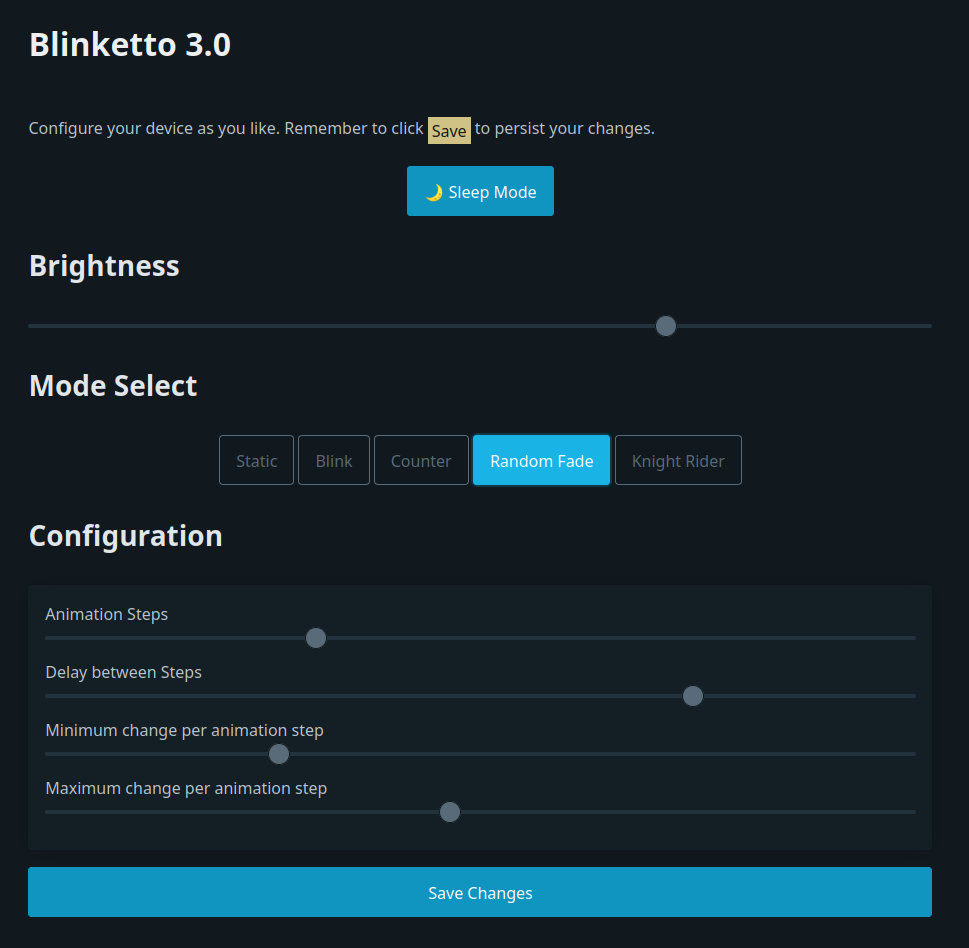
Blinketto’s code was rewritten from scratch and now comes with a super basic web interface that allows you to configure the blinking patterns in real-time and switch between different modes. The webserver is single-threaded and very slow, but functional for that one time in a year when you want to demonstrate it to a visitor. Because other than that, I realized that I will not tweak the blinking pattern on a daily basis.
The End?
And this version, 4.0r2, is what has been happily “in production” in my living room for years now.
Lessons learned
- Designing PCBs is really fun, like a puzzle for grown-ups. As I only deal with low DC voltages and currents, I can get away with many sub-optimal layouts and over time I learned more and more from YouTube.
- PCB fabrication in China is super cheap, reasonably fast (I usually had my PCBs in my hand at most 2 weeks after ordering them, and this is without any kind of express shipping). The quality is more than enough for my purposes. I tried German PCB manufacturers and while their turnover time was of course much quicker (less than a week), it was also considerably more expensive and there wasn’t really a bump in quality, either.
- I spent way too much time worrying about heat. The PixelPals consume far less energy than I thought, plus with blinking and other lighting patterns, not all 8 are on full brightness all the time.
- It’s entirely fair to modify the footprints in KiCAD to make soldering easier. If you cannot to QFN packages with your soldering iron, maybe just make the footprint a bit larger? However you should first investigate if a better package is available for your chip.
- Putting the Bill of Materials (BOM) on the backside of my PCBs helped a lot in quickly soldering them. No more losing papers or mixing them up between revisions, just look at the PCB and you know all you need.
- Always, always, always have some sort of debugging output for yourself. Even if it’s just a single LED that you can make blink in different patterns to signal what’s going on.
- I tried cheaper FTDI-alternative chips, but they weren’t really stable for me. Some seemingly just died, others had timing issues. As much as FTDI is disliked, their chips are just great and simply work. In the future I would not attempt to use alternative chips again, at least not until I would understand their failure modes better and would be better at debugging PCBs/electronics. Peace of mind and simplicity are really more important to me here, plus I do not build hundreds or thousands of PCBs, where the price might really add up. And yes, most of the FTDI adapters I bought on Amazon where fakes.
The full code, schematics and PCB design files are available on Codeberg.